Why the Layout Matters
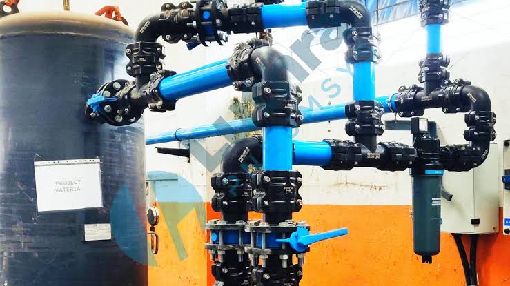
Compressed air distribution is more than a route between a compressor and a tool. The compressor, receiver, dryer, filters, piping, hoses, valves, and compressed air fittings work together to ensure the equipment receives the pressure and air quality it needs. A poorly planned network can create inconsistent pressure at remote workstations, complicate repairs, and encourage operators to raise system pressure to compensate for restrictions.
Pressure loss deserves attention because restrictions in the distribution system make it harder to deliver the required pressure at the point of use. Natural Resources Canada notes that undersized distribution piping can create significant pressure loss and identifies piping, hoses, valves, filters, and quick connectors as common places to inspect when improving a system. Its compressed air system guidance is a useful neutral reference when evaluating efficiency opportunities.
Map the Existing System
Before redesigning a line or ordering materials, document what is already in place. Walk the facility rather than relying exclusively on legacy drawings. Machines move, production cells expand, and disconnected equipment may leave behind unused branches that still affect service access and system flow.
What to record on the system map
- Compressor, receiver, dryer, and filter locations.
- Main headers, branch lines, pipe materials, and nominal diameters.
- Valves, drains, regulators, gauges, flexible hoses, and connection points.
- Equipment airflow requirements and areas with intermittent or high demand.
- Pressure readings at the compressor room and at the most remote points of use.
Label each section clearly and note whether it remains in service. This map becomes the baseline for sizing decisions, maintenance planning, leak surveys, and future expansions.
Choose a Layout That Fits the Facility
A straight-line layout can be practical in a small shop with a compact process flow and limited points of use. Air travels from the source through a main header, then into branches and drops. The approach is simple, but distant users may be more exposed to pressure variation as demand changes.
A looped arrangement provides multiple routes for air to reach portions of the network. That can help distribute the flow when several machines operate simultaneously. The appropriate choice depends on building dimensions, peak demand, process criticality, maintenance access, and the likelihood of expansion. A loop is not automatically necessary, but it is worth evaluating for facilities with broad distribution needs.
Size Piping Around Real Demand
Pipe size should reflect actual demand, not simply the compressor outlet connection. A line that appears adequate at low production may become restrictive when multiple machines, blow-off stations, or pneumatic tools run simultaneously. Include the full route length and the resistance introduced by fittings, treatment equipment, and end-use connections.
- List every current point of use and its airflow requirement.
- Identify which loads operate simultaneously during peak production.
- Measure the longest practical path from the source to the end user.
- Account for valves, elbows, tees, filters, regulators, and hose connections.
- Set an acceptable pressure-drop target based on equipment needs.
- Include a reasonable capacity for planned additions before finalizing the diameter.
Designing for foreseeable growth can avoid later shutdowns and replacement work. A qualified designer should confirm pressure-drop calculations and verify that selected materials, joining methods, supports, and components are appropriate for the operating conditions.
Reduce Pressure Loss at Every Turn
Pressure loss accumulates across long runs, narrow sections, abrupt direction changes, partially restrictive valves, dirty filters, undersized couplers, and lengthy hoses. Each component may seem minor on its own, but combined, the restrictions can leave an end user short of pressure during peak demand.
- Keep headers and branches as direct as the facility allows.
- Limit unnecessary elbows, tees, dead-end branches, and sudden diameter reductions.
- Use full-flow valves where main-line isolation is needed.
- Select filters, regulators, hoses, and couplers for the anticipated maximum flow.
- Remove abandoned branches or isolate them with properly located valves.
- Inspect filters and regulators for excessive differential pressure.
In a plant piping case study, a foundry addressed inefficient routing and pressure-loss issues as part of a broader compressed-air optimization effort. The practical lesson is to investigate the distribution path before assuming the compressor lacks capacity.
Plan for Moisture and Drainage
As compressed air cools in the distribution system, moisture can condense. Without suitable drainage and air treatment, water can reach tools and processes, contribute to internal corrosion, and interfere with consistent air quality. Piping layout supports moisture management, but it does not replace the need for correctly selected dryers, filters, separators, and drains.
- Slope horizontal mains toward planned low points where condensate can be removed.
- Install drains at low points and inspect automatic drains regularly.
- Take branch drops from the upper portion of the main line where practical.
- Provide drip legs below drops so water can collect away from the connection.
- Keep condensate discharge arrangements consistent with site environmental and safety requirements.
Build Better Drops and Connection Points
A drop should deliver air conveniently without creating a water trap or forcing technicians to shut down an entire area for basic service. Place regulators near the equipment they serve, minimize unnecessary hose length, and keep connections away from traffic lanes, sharp edges, excessive heat, and moving equipment.
- Can the drop be isolated independently?
- Is there a drainable low point below the takeoff?
- Can technicians safely reach the valve, drain, and fittings?
- Does the hose route avoid damage and trip hazards?
- Is the connection sized for the equipment’s peak flow requirement?
Leave Room for Future Growth
Production layouts rarely remain fixed. New equipment, added shifts, and relocated work cells can turn a once-adequate network into a bottleneck. Reserve physical room for additional branches, install isolation valves at logical zones, and consider capped connection points where expansion is likely. Also, leave service clearance around receivers, drains, filters, and valves.
Test and Maintain the Network
Commissioning should confirm that the modified or new system meets requirements under realistic conditions. Inspect joints, supports, valves, and connections; test according to approved site procedures; check for leaks; and compare pressure at the source with readings at remote points during expected peak demand. Record these baseline measurements and update the system map when work is complete.
Ongoing maintenance should include scheduled leak checks, drain inspections, filter service, hose inspections, and periodic pressure monitoring. Tracking changes over time helps identify restrictions before they affect production.
Final Checklist
- Has the entire compressed air network been mapped?
- Are present and anticipated air demands documented?
- Has pipe sizing been reviewed for peak demand and pressure drop?
- Are routing, drainage, isolation, and service access addressed?
- Have unnecessary restrictions and unused branches been removed or isolated?
- Has the completed network been tested at peak demand?
A dependable compressed air network begins with deliberate routing and realistic demand data. Correct sizing, controlled moisture, accessible drops, and consistent maintenance can help a facility deliver stable air where it is needed while reducing avoidable waste.